


Parameter |
Symbol |
Conditions |
Min. |
Typ. |
Max. |
Units |
Radiant Flux |
Φe |
IF=700mA |
135 |
760 |
mW |
|
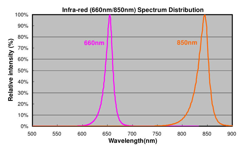
Peak Wavelength |
WLP |
IF=700mA |
640 |
870 |
nm |
|
Forward Voltage |
VF |
IF=700mA |
1.2 |
3.2 |
V |
|
Thermal Resistance JunctionTo Board |
RthJ-B |
IF=700mA |
13 |
°C/W |
||
Temperature Coefficient of Forward Voltage |
ΔVF/ΔT |
IF=700mA |
2 |
mV/°C |
||
Reverse Current |
IR |
VR=5V |
10 |
μA |
||
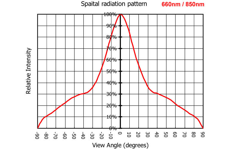
Viewing Anglet Note[1] |
2θ1/2 |
IF=700mA |
50 |
60 |
70 |
Degree |
Parameter |
Symbol |
Conditions |
Min. |
Typ. |
Max. |
Units |
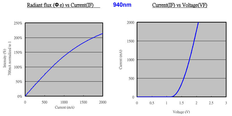
Radiant Flux |
Φe |
IF=700mA |
135 |
760 |
mW |
|
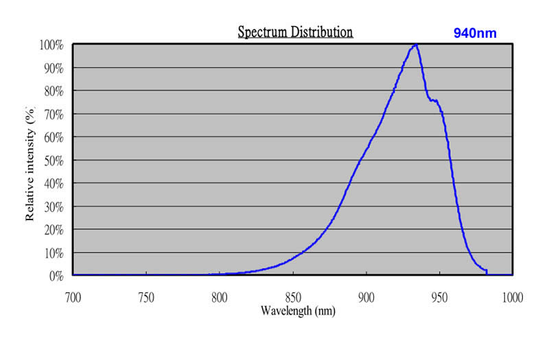
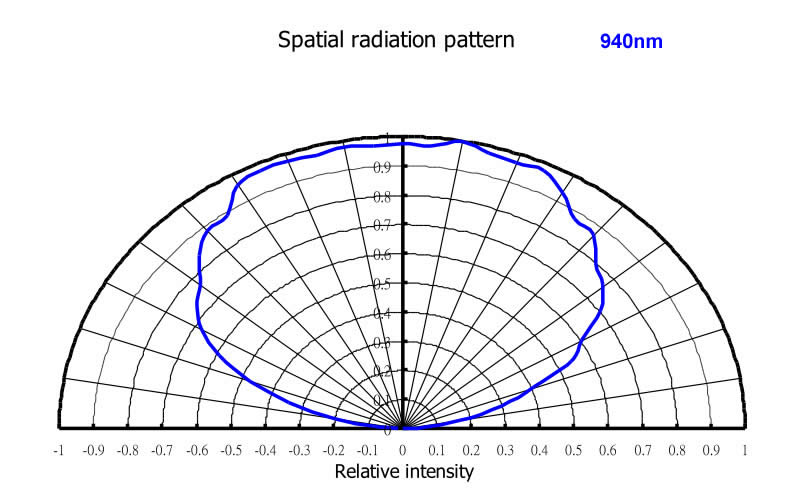
Peak Wavelength |
WLP |
IF=700mA |
935 |
955 |
nm |
|
Forward Voltage |
VF |
IF=700mA |
1.2 |
3.2 |
V |
|
Thermal Resistance JunctionTo Board |
RthJ-B |
IF=700mA |
13 |
°C/W |
||
Temperature Coefficient of Forward Voltage |
ΔVF/ΔT |
IF=700mA |
2 |
mV/°C |
||
Reverse Current |
IR |
VR=5V |
10 |
μA |
||
Viewing Angle Note[1] |
2θ1/2 |
IF=700mA |
130 |
140 |
150 |
Degree |
Parameter |
Symbol |
Conditions |
Units |
Power Dissipation |
PD |
3 |
W |
Continuous Forward Current |
IF |
700 |
mA |
Peak Forward Current Note[2] |
IF(Peak) |
1000 |
mA |
LED Junction Temperature |
Tj |
120 |
/°C |
Reverse Voltage |
VR |
5 |
V |
Operating Temperature Range |
Topr |
30°C To +80°C |
|
Storage Temperature Range |
Tstg |
-40°C To +100°C
|
|
Manual Soldering Temperature |
Tsol |
260°C±20°C For 3-5 Seconds
|
|
ESD Sensitivity |
ESD |
2000V HBM |
|


Profile Feature |
Typical parameters |
Average Ramp-Up Rate (Ts max to Tp) |
3 °C/second max. |
Preheat Temperature Min (Ts min ) |
150 °C |
Preheat Temperature Max (Ts max ) |
200 °C |
Time (ts min to ts max ) |
60-180 seconds |
Time maintained above Temperature (TL) |
217 °C |
Time maintained above Time (tL) |
60-150 seconds |
Peak/Classification Temperature (Tp) |
260 °C |
Time within 5 °C of Actual Peak Temperature (tp) |
5 seconds |
Ramp-Down Rate |
6 °C/second max. |
Time 25 °C to Peak Temperature |
8 minutes max. |

W1 |
W2 |
H1 |
H2 |
L |
16.5 |
9.6 |
8.0 |
3.4 |
424.0 |
±0.2 |
±0.2 |
±0.2 |
±0.2 |
±2.0 |

M |
N |
W |
W1 |
H |
K |
S |
Φ330.0 |
Φ99.5 |
24.4 |
29.0 |
Φ13.5 |
10.75 |
2.5 |
±1.0 |
±1.0 |
±1.0 |
±1.0 |
±0.5 |
±0.5 |
±0.5 |
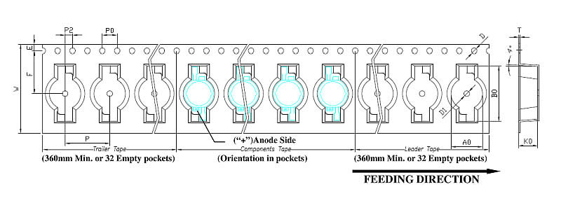
W |
P |
E |
F |
P2 |
D |
D1 |
P0 |
A0 |
B0 |
K0 |
T |
24.0 |
12.0 |
1.75 |
11.5 |
2.0 |
1.5 |
1.5 |
4.0 |
8.45 |
15.0 |
5.10 |
0.37 |
±0.3 |
±0.1 |
±0.1 |
±0.1 |
±0.1 |
±0.1 |
±0.25 |
±0.1 |
±0.1 |
±0.1 |
±0.1 |
±0.02 |
Color |
Order Code |
Peak Wavelength (nm) |
|
Min |
Max |
||
IR
|
UVA-003-660 |
655 |
665 |
UVA-003-850 |
845 |
855 |
|
UVA-003-940 |
935 |
945 |
|

